2. The DVI (Digital Visual Interface)
The DVI (digital visual interface) or digital video interface is a connection system for transmitting video signals in digital format. Its mission is to replace the old analog system used by VGA CRT monitors (Cathode Ray Tube) and provide the new device displays, LCD monitors, video screens LCD / plasma and digital projectors to connect personal computers to obtain maximum image quality they can offer these digital devices.
It was developed by the consortium DDWG (Digital Display Working Group) and the Working Group for Digital Screen consists of large companies in the consumer electronics and information technology as Intel, Compaq, Fujitsu, Hewlett Packard, IBM, NEC and Silicon Image with the aim of providing a joint solution of connection between the modern digital displays and personal computers (PC).
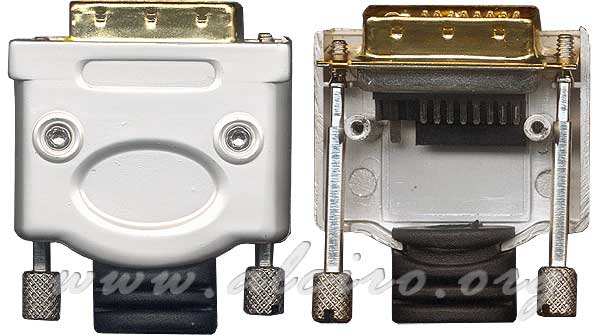
Internal detail of a male DVI connector.
2.1. DVI Connector Types
The DVI (Digital Visual Interface) is designed for transmitting digital video signals, but to maintain compatibility with the analog system has been equipped with additional whiskers. Depending on your application, the connector may have more or less pins. Can be found only analog connectors (DVI-A), only digital data channel or dual channel data (DVI-D) and the combination of both analog and digital (DVI-I). The following figures show the pinout of the different DVI connectors female.
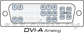
DVI-A Analog (Analog)
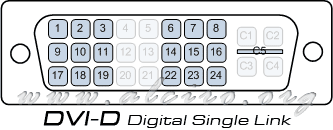
Digital DVI-D single link (Digital Single Link)
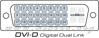
Digital DVI-D Dual Link (Digital Dual Link)
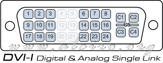
DVI-I Digital and Analog single bond (Digital & Analog Single Link)
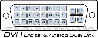
DVI-D Digital and Analog Dual Link (Digital & Analog Dual Link)
2.2. DVI Connector Pinout
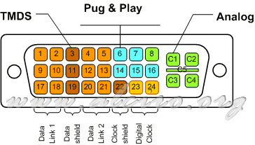
DVI Connector Pinouts
The DVI connector is divided mainly into three areas:
- TMDS. (Transition Minimized Differential Signaling) or Transition Minimized Differential Signal similar to communication systems balanced. Marked on the figure by the brown color has four twisted pair cables one for each primary color video red, green and blue. Each two pairs have a mass of specific protection marked in dark brown. The video signal is synchronized with a pair of twisted wires in light brown line has its own mass. With a video link can transmit high-definition HDTV signal (1920 × 1080) at 60 Hz (139 MHz) for better definitions and better refresh the DVI connector includes a second link in combination with the former provides resolutions higher than HDTV HDTV (1920 × 1080) at 85 Hz (2 × 126 MHz) or WQXGA (2560 × 1600) at 60 Hz (2 × 135 MHz), among others.
- Pug & Play. Marked in blue has a number of lines that highlight the DDC (Display Data Channel), serial connection with pin I2C Bus SDA (data) and SCL (clock). Are used to detect and display settings when connecting to a computer.
- Analog. Analog system, marked in green features a pin (pin) for each RGB primary color red, green and blue analog sync with the digital connector makes it compatible with the analog system, reaching a bandwidth of 400 MHz
Pin (pin) DVI connector.
| Pin | Signal | Description |
| 1 | Data 2 - | TMDS Digital Link 1 - |
| 2 | Data 2 + | Link TMDS 1 digital + |
| 3 | Mass data 2 / 4 | Mass protection |
| 4 | Data 4 - | TMDS Digital Link 2 - |
| 5 | Data 4 + | Link TMDS 2 digital + |
| 6 | SCL | DDC Clock |
| 7 | SDA
| DDC Data |
| 8 | Analog vertical sync | |
| 9 | Data 1 - | TMDS Digital Link 1 - |
| 10 | Data 1 + | Link TMDS 1 digital + |
| 11 | Mass data 1 / 3 | Mass protection |
| 12 | Data 3 - | TMDS Digital Link 2 - |
| 13 | Data 3 + | Link TMDS 2 digital + |
| 14 | +5 V | Energy for monitor standby |
| 15 | Mass | Return to 14 and analog sync |
| 16 | Hot plug detection | |
| 17 | Data 0 - | TMDS Digital Link 1 - and digital sync |
| 18 | Data 0 + | Link TMDS 1 digital + and digital sync |
| 19 | Mass data 0 / 5 | Mass protection |
| 20 | Data 5 - | TMDS Digital Link 2 - |
| 21 | Data 5 + | Link TMDS 2 digital + |
| 22 | Mass of watch | Mass protection |
| 23 | Clock + | TMDS Digital clock + (Links 1 and 2) |
| 24 | Clock - | Digital TMDSReloj - (Links 1 and 2) |
| C1 | Red analog | |
| C2 | Green analog | |
| C3 | Blue analog | |
| C4 | Analog horizontal sync | |
| C5 | Ground (analog) | Return for analog signals |


