5.1. The physical layer
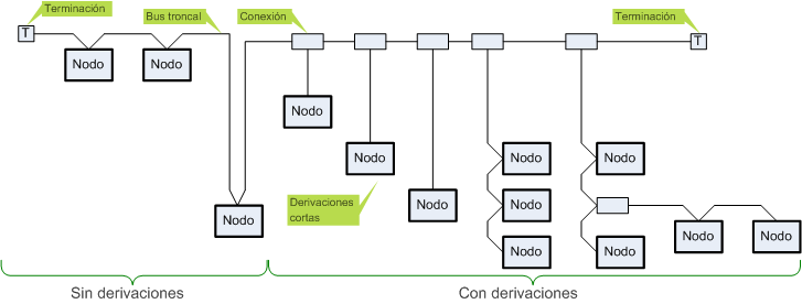
The bus topology is linearly from beginning to end of the network where the loads are placed finishers from the end of the bus, this configuration represents the backbone of the bus which will allow small leads to a certain length.
Being a network with built-in power cord itself, the length and thickness of the wire section or used influence the speed of communication, the following table determines the length of cable in terms of communication speed and type of cable used.
| Data Rate | 125 Kbps | 250 Kbps | 500 Kbps |
| Thick trunk cable length | 500 m | 250 m | 100 m |
| Trunk length with thin wire | 100 m | 100 m | 100 m |
| Trunk length flat cable | 380 m | 200 m | 75 m |
| Maximum length of derivation | 6 m | 6 m | 6 m |
| Total length in leads | 156 m | 78 m | 39 m |

DiviceNet bus topology nodes
Connectors
Depending on the type of device and the need for point of use can use various types of connectors sealed or open to the DeviceNet network. Closed ones available is larger connectors (mini-style) or small (micro-style). In the open connectors can be found in enchufadle connector block or blocks with screw connection which enables manual connection of cables.
| Wire Color | Identity Wire | Round Usage | Usage Flat |
| white | CAN_H | signal | signal |
| blue | CAN_L | signal | signal |
| Bars | drain | shield | n / a |
| black | V- | power | power |
| network | V + | power | power |
Details of standard connectors for DeviceNet networks.

DiviceNet connectors

DiviceNet connectors
5.2. The data link layer
The data link layer is defined by the specifications for chip CAN microcontrollers.
(CAN or CAN-bus Controller Area Network) is a standard protocol bus network topology designed to allow microcontrollers and peripheral devices communicate with each other directly without a host computer.

DiviceNet data frame format
5.3. The network layer and transport
-

DiviceNet identification bits


