4.2. Component Editing
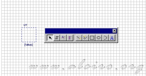
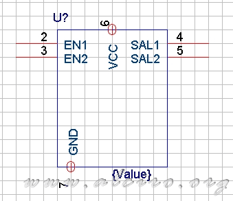
After setting the properties of the component, Orcad opens a road edition, which is drawn the body of the component, represented by a dashed rectangle. Inside the body must put all the graphic elements that define it. On the periphery are placed the pins (Pins), following a logical order, the entry on the left and right output (if the component allows it).
There are different elements to place inside and outside the component body, represented in the toolbar.

Toolbar to edit a component
4.2.1. Component body
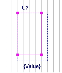
If the component is an integrated, draw a rectangle that measures necessary to accommodate all the pins (Pins). When the symbolism of the component is different from the square, draw the component with the necessary drawing elements within the body (dashed lines).
The reference U? And the name {Value} are set automatically from the properties listed above.
Note: You can not draw outside the body of the component, the program itself does not.

Main component
4.2.2. Pins (Pins)

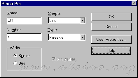
Edit pin pin
Pressing the button (Pin) for the toolbar appears a working window to edit the properties (Pin), of which stand out.
- Name: Name (Pin). Alphanumeric string.
- Number: Number of pin (Pin).
- Shape: Appearance (Pin).
- Clock: clock signal.
- Dot: Signal denied.
- Dot-Clock: Clock denied.
- Line: Line (Default).
- Shor t: Short line.
- ZeroLeng: Not long.
- Type: pin type, as the signal travels.
- 3 State: Three states (digital circuits).
- Bidirectional: signals in both directions (emission and absorption).
- Input: Input signal.
- Open Collector, Open Collector.
- Open Emitter: In open emitter.
- Output: Output.
- Passive: Passive, acts as a receptor (Default).
- Power: Supply Pin.
- Width: Width of the conductor. Specifies whether the (Pin) is connected to a string (scalar) or a bus (Bus).
Note: when identifying the type (Pin) must be known with certainty to establish operation between the different types available. If unknown function (Pin), you have to place the default type (passive). When making an outline, two (Pins) output type (output) can not be connected to each other, since the program interprets this as a short circuit. You have to be careful when designating (Pins) to types (Output, 3 State and Bidirectional).
When a (Pin) output is situate as (Power).

New Component


