1. Graphic Elements
Different elements can be found in a schema.
1.1. Components (Parts)
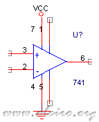
The electronic components that are part of a scheme, they are in the libraries of each manufacturer, such as resistors, capacitors, integrated circuits and so on.
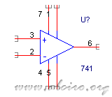
Component Parts
1.2. Wire (Wire)
The electrical connections between different elements of the scheme.
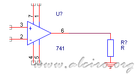
Wire thread
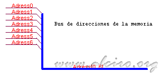
1.3. Set of wires (buses)
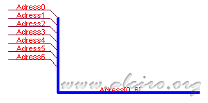
Set of threads within a single driver and a conductor tube.
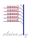
Bus wire set
1.4. Unions (Juctions)
Indicate a physical connection between wires and buses.
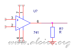
Juctions Unions
1.5. (Power Objects)
Indicate the pins that attach to a power source. Power Object name determines which terminal is plugged. Two Power Object with the same name are electrically bonded to each other.
Power supply Objects
1.6. Connection between sheets (Port Module)
The Port Module allows signal connections between different schemes leaves flat or hierarchical.
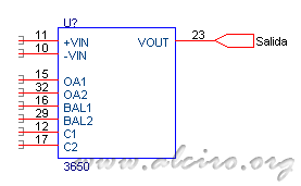
Port Connection Module sheets
1.7. Symbols sheet (Sheet Symbols)
Elements for the realization of hierarchical schemes. You can start from a block diagram or an outline with blocks, each block representing another scheme that is in a different sheet.
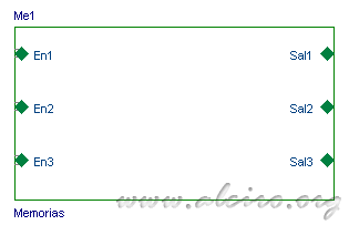
Sheet Sheet Symbols Symbols
1.8. Tags (Label)
Tags are information provided to the program to identify tracks of wiring (wires and buses). These represent connections between the wires or buses that have the same name. Represent an easy way to make connections, but they are only valid within the same sheet.
Label cloud
1.9. No Connection (No Connection)
In some elements such as integrated circuits, it is sometimes necessary to make the air any pin. When performing any reports of electrical connections of the scheme, the program gives a warning to all the pins are not connected, indicating a possible error or neglect. Placing the item no connection, this error does not occur because it assumes that the pin is in the air.
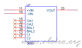
No Connection No connection
1.10. Text (Text)
Is used to add explanatory notes and labels to the scheme. Do not be confused with a neck label (Label), this makes an electrical connection, while the text.
Text Text
1.11. Box (Title Block)
Plane box outline, indicating the company, the name of the scheme, the size and number review.

Title Block box
1.12. Parties on the elements
Representation of body parts of various elements that form an outline.
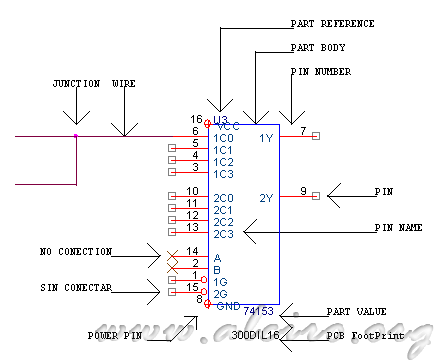
Component parts
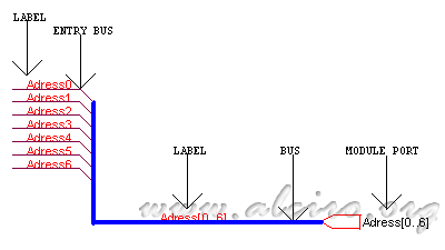
Connection components

Parts of the sheet of symbols and the box


