4. Smart home automation installations in dwellings
In this section of detailed examples of smart home automation installations in dwellings, based on the wiring diagram located on the floor plan details a possible home automation installation by microHomeLan.
4.1. Automation of a room with automation
Example of home automation installation in a room with mixed lighting using LEDs LEDs and conventional lamps.
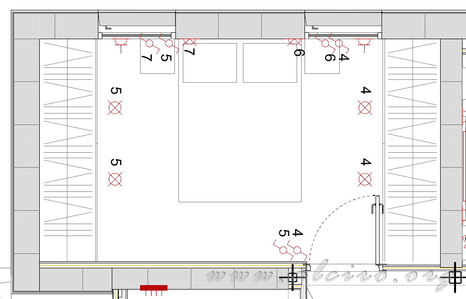
The following chart details the physical layout of the points of light and the elements of traditional control by switches or switches.
The light points are indicated by the following values.
- 4. Led lighting the right side of the room.
- 5. Led Lighting the left side of the room.
- 6. Lighting bedside lamp right.
- 7. Lighting bedside lamp right.
The switches associated with the dots are replaced by buttons (no need to be in power).

Istalación room for home automation
Domotic
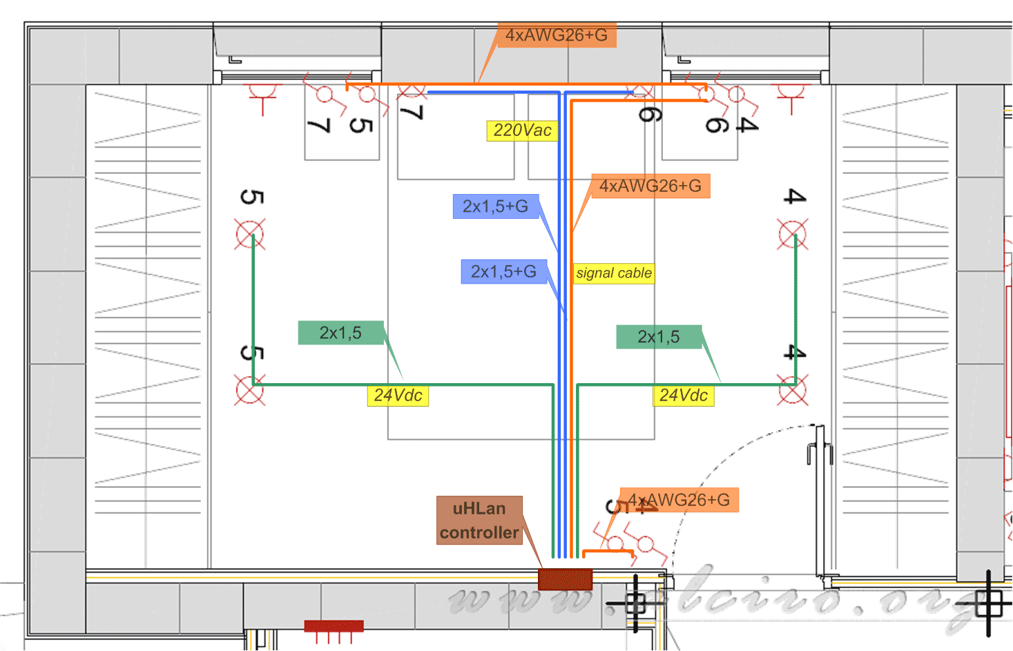
The following figure shows a possible distribution automation installation of a room. The home automation controller is integrated in a junction box in the room, usually located in the most appropriate place to minimize the total length of the cables, resulting in lower material costs and reduced losses by Joule effect. However, the situation of the case is subject to many structural factors conditioning.
For installation you fit the best route is through the ceiling, a place that provides quick access to all points of the room and avoids the creation of races / chases.
The home automation is considered as an element of automation in homes. See section FACILITIES AUTOMATION SYSTEMS, ENERGY MANAGEMENT TECHNICAL AND SAFETY HOUSING AND BUILDINGS (ITC-BT-51) of REBT.
Power Cables
- 4. 2x1, 5mm 2 (minimum) Led Lighting the right side of the room.
- 5. 2x1, 5mm 2 (minimum) Led Lighting the left side of the room.
- 6. 2x1.5mm 2 + ground (minimum) Lighting bedside lamp right.
- 7. 2x1.5mm 2 + ground (minimum) Lighting bedside lamp right.
The power cables are divided into two groups, those working to 220Vac (6 and 7) and those working to 24Vdc (4 and 5), both are subject to electrical regulations in force in each country. In our case, the low-voltage electrotechnical Regulation (s) considers the automation network cables and low voltage installations. See section A VERY LOW VOLTAGE EQUIPMENT (ITC-BT-36) of REBT.
RETB, Article 4. Classification of stress. Frequency networks.
1. For the purposes of the requirements of this regulation, low voltage electrical installations are classified as nominal voltages to be allocated, as follows:
| AC (RMS) | DC (Arithmetic Mean) |
| Low voltage | A ≤ 50V | A ≤ 75V |
| Usual stress | 50 <A ≤ 500V | 500 <A ≤ 1000V |
| Special voltage | 75 <A ≤ 750V | 750 <A ≤ 1500 |
Control Cables
- UTP 2, 4, 8 Conductor + mass of AWG22 to AWG26 section
The control cables do not have to have very strict specifications as they work to 5V with a current less than 1mA, any small communications cable signal is valid for this function.
To protect the drivers control of electromagnetic interference can be shielded cable of type FTP

Installation of cables in the room automation
Control program room lighting
Amplifier
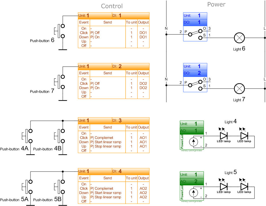
- DO1 Digital Output 1 (relay 10A) of the Unit1 connected to a bedside lamp right 6.
- DO2 digital output 2 (relay 10A) of the Unit1 connected to a bedside lamp left 7.
- 1 analog output AO1 (PowerLed) of the Unit1 connected to two LED lamps 4 (<12V each).
- 1 analog output AO2 (PowerLed) of the Unit1 connected to two LED lamps 5 (<12V each).
Control
- 1 digital input DI1 of the Unit1 connected to the push buttons 6.
- DI2 Digital Input 2 of the Unit1 connected to a push 7.
- 3 digital input DI3 of the Unit1 connected to buttons 4.
- DI4 digital input 4 of the Unit1 connected to a push 5.
Program
When doing a short press <0.25 sec in the button Click event occurs that is used to send the shutdown command, Off process. If you perform a long press and sustained> 0.25 Ins Down event occurs that is used to send the activation order, On process. If you perform a long press turns on the lamp, if you perform a short press turns off the lamp. See section 3.1.3.
When performing a long press starts smooth linear ramp, when the lighting is right, release the button, it stops the ramp and store the value. When doing a short press turns on or off the LED prior stored value. To switch back lighting only has to begin the process of linear ramp holding the button, and so on. See section 3.4.4.

Istalación control program room smart home automation


