1.1.5.1. Completion of the RS-485 bus network automation
Uhlan automation network consists of a series of home automation controllers connected in series via the RJ45 connectors to form an RS-485 Bus-type topology
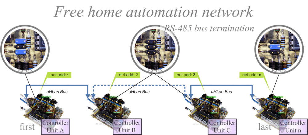
To maintain a proper impedance at the communication bus has been arranged in a terminating resistors formed by R2, R3, R4 and R14, which are connected to the line of home automation network through a switch JP1 (composed of three jumpers). By keeping the communication bus with a load balanced and appropriate are possible to the drivers of home automation network to work with long cable lengths of 500m, 1000m.
In the home automation network Uhlan are three possible configurations for controllers based on their position in the bus comunicaciones.a
1 The first home automation network controller.
This element has been to connect two bridges, as shown in the figure below. These jumpers set a reference level of intention on the bus, to set the logic levels and avoid communication problems when the bus is in high impedance state or resting.
The first network controller always have this configuration, even if one works with home automation.
2 The ultimate controller for home automation network.
For this home automation controller is not needed to establish a logical state for the network, but if necessary, load the bus with a resistance of 120 ohms, to balance the impedance of cable communications. Be done by the central bridge JP1, as shown.
3 rd Central Middle automation.
These home automation centers do not need any type of bridge as the communication network is loaded and balanced on both ends of RS-485 bus, enabling two-way communication (half-duplex) between all the drivers for home automation network.
For working with large distance are advised to intermediate home automation centers located as close as possible to the beginning or end of the network, where the communications bus signal is of better quality. Although not strictly necessary

Termination of RS-485 bus home automation network
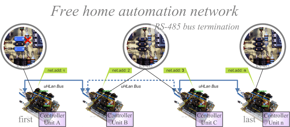
Small home automation network distance <100m
When home automation network is small, with cable lengths exceeding 100 meters may be impaired bus load resistors at the beginning and end of this, as shown in the figure below. This minimizes the consumption RS-485 bus.
In the first home automation controller must be left connected the jumpers on JP1 to set the bus state of automation, and can eliminate the load resistor R14. In the end home automation network, as in intermediate plants have not put any jumper (Jumper).
If the home automation network is in an area affected by electromagnetic interference is much better to use the network termination system automation described above.

Termination of RS-485 bus home automation network <100m
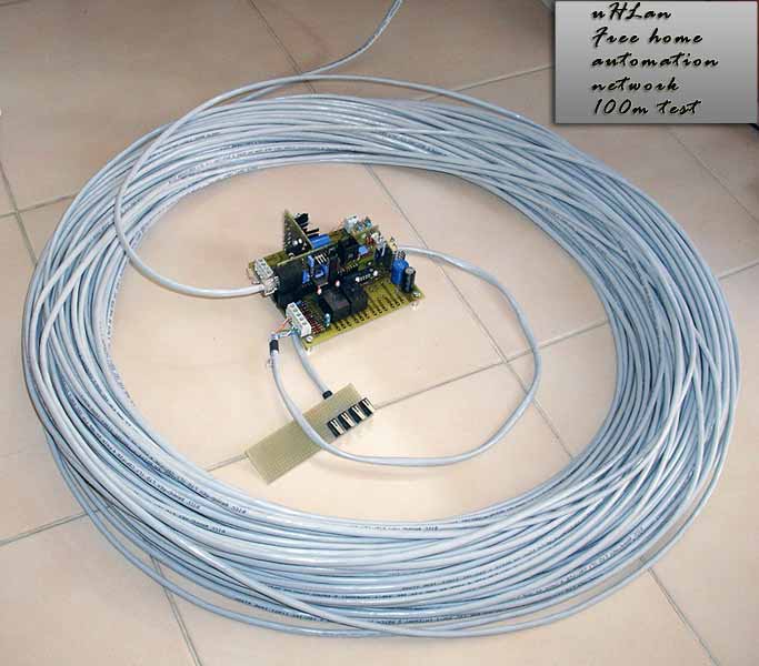
Test run 100 meters
To check the operation of the station without termination of bus automation has made a test using a standard ethernet cable with a small secion (AWG 26) as shown in the figure below.
Test Conditions
- Cable length: 109 meters
- Cable type: 4 pair 26 AWG Category 5 FTP
- Supply voltage: 24 V (Start Bus)
- Connection Type: 2 nd (no bus terminating resistors RS-485)
Consumption
| Terms | Tension in the central (V) | Lost in the cable (V) | Consumption (mA) |
| Normal operation | 23.84 V | 0,16 | 10.52 mA |
| With 1 active relay | 23.58 V | 0,42 | 27.9 mA |
| With 2 relays active | 23.37 V | 0,63 | 45 mA |
The automation plant operation under these conditions the test is correct, and losses in the cable can be considered negligible. If we connect a large number of home automation centers we recommend using 24 AWG cable type.
Recommended cable
- Small distance <= 100m, Category 5 UTP or FTP, AWG 22, AWG 24, AWG 26
- Great distance> 100m: Category 5 FTP, AWG 22, AWG 23, AWG 24
For most home automation installations in apartments or houses cable length not exceed the 100m, so the configuration without terminating resistors and any cable network as a Cat 5 UTP AWG 24 is sufficient for proper operation.
In installations with long cable lengths (500 to 1000m), power losses in the bus can be significant especially if you install a large number of home automation centers. In this case, use a larger wire Cat 5 FTP section AWG 22.
You can work with any standard network cable if you turn off via the bus (power over LAN) and home automation are fed independently.

Functional testing of a prototype home automation controller working with a 100 meter cable


