1.1.5. Uhlan bus

Uhlan bus
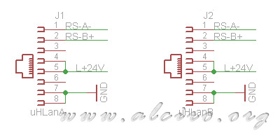
The bus consists Uhlan RJ45 connectors for UTP-22 AWG standard for transmitting the data signals while network that feeds the various units that make up the bus. Each unit CPU is equipped with two network connectors to allow cascading all the units.
J1 and J2 connectors of the RJ-45 female have 8 pins, 4 twisted pairs of wires AWG-22, 23 or 24. Pins 1 and 2 were aimed at the data line RS-485, RS-pin RS-A-and B + respectively. Pins 4 and 5 are used for power line +24 V, while the pins 7 and 8 are aimed at the ground line and power back finally frees the pins 3 and 6 are reserved for applications special food or reinforce where needed greater power consumption in the network.
RS-485 Driver

Uhlan RS-485 Driver
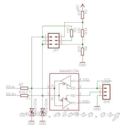
The RS-485 driver is based on an integrated circuit such as MAX-485 mounted type industrial network with bus topology. The great qualities of such drivers as its high immunity to noise and distance of up to 1200 makes it a perfect item to fit the demotic network. Pins 1 and 4, respectively RXD and TXD are connected to the pins on the microcontroller USE.
It has provided a connector for the control SV6 receiver driver to control the echo of the transmission. With a jumper between pins 1 and 2 disables the echo, and the bridge between pins 2 and 3 (default) enables the echo. For Uhlan network has to be enabled in the echo because all transmissions are checked to detect when a collision on the frames.
Protection circuit
In the cable network can produce all kinds of interference induced by electromagnetic interference, to protect the driver of network communications automation has provided a protective device formed by diodes D1, D2 and resistors R7, R10.
The diodes D1 and D2 represent protection for high voltage transients that may occur in the home automation network, consists of two (transil gods) and 600W 12V P6KE12CA-way. They protect the body produced transient lines of communication and mass.
You can optimize the circuit for more efficient protection, placing protection diodes between the lines and ground and between the lines of communication, has opted for the combination shown in the figure to minimize the cost.
The circuit has been designed with two fuses resistors R7 and R10 1Ω as an additional element of protection, if the current through them is greater than 0.5 A, the resistance will melt avoiding the deterioration of the circuit.

The resistors R7 and R10 are not strictly necessary and can therefore be replaced by a simple bridge. If the resistance is melting, the home automation is no communication until the resistors are replaced with new ones.
All of the protection element can be deleted if you use a RS-485 driver incorporating integrated ESD protection.


