1. Mainframe CPU
Mainframe CPU represents with the microprocessor control unit and communications for the network buses uHLan RS-485 and peripheral items such as touch sensors on the bus i2cBus or temperature sensors 1-wire.
The CPU is designed in an independent Board to be able to interact with different motherboards, where you can place drivers of different types according to the need for power. In this way a same CPU can be used for different actuadotes changing the firmware.
1.1. 1.0 CPU Uhlan
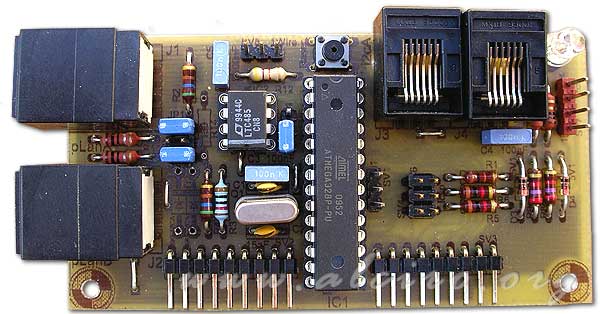
Prototype CPU core unit microHomeLan 1.0

Prototype CPU core unit Uhlan 1.0
1.1.1. Microcontroller

ATMEGA238 microcontroller core unit CPU 1.0 Uhlan
For the development of the central processing unit (CPU) has used the known ATMega328, 8bit AVR microcontroller ATMEL house Widespread in other projects on the web.
MEGA328 Features:
- High Performance, Low Power AVR ® 8-Bit Microcontroller
- Advanced RISC Architecture
- 131 Powerful Instructions - Most Single Clock Cycle Execution
- 32 x 8 General Purpose Working Registers
- Fully Static Operation
- Up to 20 MIPS throughput at 20 MHz
- On-chip 2-cycle Multiplier
- High Endurance Non-volatile Memory Segments
- 08.04.1916 / 32K Bytes of In-System Self-Programmable Flash memory progam (ATmega48PA/88PA/168PA / 328P)
- 256/512/512 / 1K Bytes EEPROM (ATmega48PA/88PA/168PA / 328P)
- 512/1K/1K / 2K Bytes Internal SRAM (ATmega48PA/88PA/168PA / 328P)
- Write / Erase Cycles: 10,000 Flash/100, 000 EEPROM
- Data retention: 20 years at 85 ° C/100 years at 25 ° C (1)
- Optional Boot Code Section with Independent Lock Bits
In-System Programming by On-chip Boot Program
True Read-While-Write Operation
- Programming Lock for Software Security
- Two 8-bit Timer / Counters with Separate Prescaler and Compare Mode
- One 16-bit Timer / Counter with Separate Prescaler, Compare Mode, and Capture Mode
- Real Time Counter with Separate Oscillator
- Six PWM Channels
- 8-channel 10-bit ADC in TQFP and QFN / MLF package
Temperature Measurement
- 6-channel 10-bit ADC in PDIP Package
Temperature Measurement
- Programmable Serial USART
- Master / Slave SPI Serial Interface
- Byte-oriented 2-wire Serial Interface (Philips I2C compatible)
- Programmable Watchdog Timer with Separate On-chip Oscillator
- On-chip Analog Comparator
- Interrupt and Wake-up on Pin Change
- Special Microcontroller Features
- Power-on Reset and Programmable Brown-out Detection
- Internal Calibrated Oscillator
- External and Internal Interrupt Sources
- Six Sleep Modes: Idle, ADC Noise Reduction, Power-save, Power-down, Standby, and Extended Standby
- 23 Programmable I / O Lines
- 28-pin PDIP, 32-lead TQFP, 28-pad QFN / MLF and 32-pad QFN / MLF
- 1.8 - 5.5V for ATmega48PA/88PA/168PA/328P
- -40 ° C to 85 ° C
- 0 - 20 MHz@1.8 - 5.5V
- Low Power Consumption at 1 MHz, 1.8V, 25 ° C for ATmega48PA/88PA/168PA/328P:
- Active Mode: 0.2 mA
- Power-down Mode: 0.1 uA
- Power-save Mode: 0.75 uA (Including 32 kHz RTC)
Oscillator (crystal system)
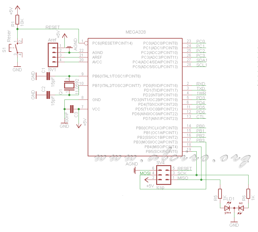
ATMega328 microcontroller can work with an internal clock or external, has chosen to use an external quartz crystal to control the working frequency more accurately. The range of frequency is a few KHz to 20MHz, has chosen a 11.0592 MHz crystal to provide high computing power and low power consumption.
Another factor in the choice of this component is its standardization and its wide use in many industrial microprocessor-based projects. The 11.0592 MHz crystal is designed to provide multiple clock speeds work of UARS or used and provide a communication speed in bauds accurate.
The microcontroller crystal is used for the operation of internal timers to generate all sequences of temporal control in communications, timers, sensors and actuators, so that the frequency of 11.0592 MHz is associated with the firmware of the project.
You can not change the frequency of the quartz crystal except by creating a specific firmware for the crystal.
Firmware programming, ICSP (In-Circuit Serial Programming)
The AT-MEGA328 microcontroller has the ability to be programmed in circuit using ICSP connection to what has been equipped with a connector for programming and to update the firmware directly on the plate, without removing chip.
For programming you a RS-232 adapter for ICSP or any programmer compatible with Atmel MEGA family.
Status Indicators
To indicate the status of communications between devices using the LED LD1 two colors (red, green) common cathode.
The current through the LED is determined by resistors R5 and R6 1k.

The indication of the stage of the communication occurs on the sending unit and the target drive, ignoring the other units that form the network.
- Green LED correct transmission
Issuer: We have sent the correct frame and has received a response (confirmation) correct.
Receiver: the frame has been received and identified the process or act properly.
- Orange LED (a) Frame or incorrect command, (b) overflow timeout
(A)
Issuer: If the recipient's response is incorrect.
Receiver: If the issuer's request is incorrect or not recognized the process or action in this unit.
(B)
Transmitter and Receiver: When you send an incomplete frame when data are expected to complete a frame and fail or take too long.
- Red LED Collision or error on the line RS-485
Transmitter and receiver-in the transmission of a frame, when the echo of the line does not match the data sent. This can happen because two units try to send data at the same time or that the communication line has a problem.


