1.1.2. Bus Connection

Communication buses Uhlan 1.0 CPU
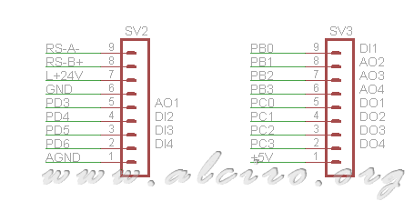
Communication systems or expansion of the CPU board is designed to connect the input and output ports of μcontrolador with different power motherboards.
The buses SV2 and SV3 of 9 pins each consist of a plug for IC-type layered post.
Connector SV2
| Number | Pin | Description | Board assignment |
| 1 | AGND | Analog ground | Mass |
| 2 | PD6 | Port D pin 6 | Digital input DI4 4
|
| 3 | PD5 | Port D pin 5 | Digital input DI3 3
|
| 4 | PD4 | Port D pin 4 | DI2 Digital Input 2
|
| 5 | PD3 | Port D pin 3 | 1 Analog output AO1
|
| 6 | GND | Digital Mass | Mass |
| 7 | L +24 V | Mains PoE | 24V, food MB
|
| 8 | RS-B + | RS-485 line B | Additional connection terminal |
| 9 | RS-A- | RS-485 A Line | Additional connection terminal |
SV3 connector
| Number | Pin | Description | Board assignment |
| 1 | +5 V | CPU Digital Power | 5V Input |
| 2 | PC3 | Port C pin 3 | 4 Digital Output DO4 |
| 3 | PC2 | Port C pin 2 | DO3 Digital output 3 |
| 4 | PC1 | Port C pin 1 | DO2 Digital Output 2 |
| 5 | PC0 | Port C pin 0 | DO1 Digital Output 1 |
| 6 | PB3 | Port B pin 3 | AO4 4 Analog Output
|
| 7 | PB2 | Port B pin 2 | AO3 Analog output 3
|
| 8 | PB1 | Port B pin 1 | 2 analog output AO2
|
| 9 | PB0 | Port B pin 0 | Digital input DI1 1
|
1.1.3. Bus 1-Wire Communications / Control

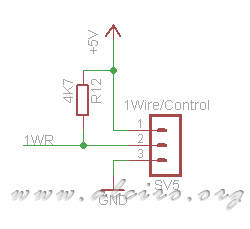
Bus 1-Wire communication / control
The connector consists of a pole SW5 three pins is for temperature sensing devices that use the communications protocol developed 1-Wire Dallas Semiconductor ( Maxim ). These 1-Wire devices communicate through a single wire forming a network of bus type, although it has 2 pins for power, the devices can be powered beams of the data line, running minimized 2-wire connection, and mass data.


