4.3.6. Types of current control
4.3.6.1. Pulse width modulation (Pulse Width Modulation)
Control by pulse width modulation is to adjust the relationship between the driving pulse width and the blockade, the driver power depending on the desired intensity.

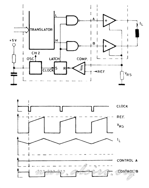
Figure 4.42. Chopper bipolar pulse width modulation (PWM).
Figure 4.42. you can see a typical PWM control circuit. The base of the oscillator circuit as fixed time, which determines the frequency of the circuit. It attacks a flip-flop RS, acting on the line of Seth. Each see that there is a clock line activated in September RS flip-flop, which results to activate the drivers connected to the Q output line, feeding the winding. The current flowing through the motor winding resistance and sensor Rs. When the drop in this resistance equals the reference voltage Vref, the comparator acts on the scale and reset the flip-flop. The output Q is set to zero and the driver is switched off, giving way to the recycling stream. The time sequence of activation and unemployment depend on the desired intensity and therefore the reference voltage. The sum of both times is always fixed and corresponds to the period of the oscillator.


