1.3. Hybrid Stepper Motors
The hybrid stepper motors operate by combining the principles of permanent magnet motors and variable reluctance, trying to get the features that stand out in every one of them. Combined obtained small pitch angles and high torque with small size.

Figure 2.13. Structure of the rotor of a hybrid engine.
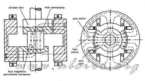
The nature and form of the stator is almost equal to that of the other models of stepper motors and permanent magnet variable reluctance. The major differences are in the rotor structure, consisting of a cylindrical magnetic disk in longitudinal axis, as shown in Figure 2.13, it is highly magnetized producing a unipolar flow as shown in Figure 2.14 (a). The magnetic lines generated by the magnet is driven by two cylinders attached to the ends of each of its poles (north and south). Usually made of sheets of ferromagnetic material and tooth, are the poles of the rotor.
The magnetic flux generated by the stator windings flows as shown in Figure 2.14 (b).
The hybrid engine produces a reluctance torque by force, like the variable reluctance motor. The difference is that the type of excitation used. In the variable reluctance motor, the excitation is produced only by winding, while the hybrid engine is a joint excitation winding and the magnet.
In Figure 2.14 we have the basic layout of a hybrid motor step angle of 90 degrees. For smaller pitch angles, just increase the number of poles of the rotor and stator. The potential number of steps are limited by the number of poles that can hold the stator and the number of teeth each.

Figure 2.14. Transversal and longitudinal section of a hybrid of 90 degrees, mostrnado the path of magnetic flux lines produced by the excitation of a winding.


