2.2.5.1. Model of a hybrid stepper motor
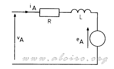
The first step in the calculation of the pair is set the model for a motor phase (Figure 3.21). A hybrid engine has two independent wound stages mounted on the stator, the model for each phase including the resistance and inductance of the coil. The resistance of the wire and the winding inductance characteristics we are determined by the manufacturer.

Figure 3.21. Model circuit for one phase of a hybrid engine.
To complete the model must include the induced voltage in the winding of the phase by the action of the rotor. This tension is caused by the flow generated by the permanent magnet, varying sinusoidal with respect to the position of the rotor. The flow induced in the phases A and B with a motor with the rotor teeth d can be expressed as:
\\ \psi _B\ =\ \psi _M*sin(d*\theta-\frac{\pi }{2} )) (3.15)
(3.15)
ψm the maximum flow being induced in each winding. When the rotor moves at the speed dq / dt, the induced voltage in the winding of the phase is equivalent to flow changes induced.
*\frac{\partial \theta }{\partial t}\\ e_A\ =\ \frac{\partial \psi _B}{\partial t}\ =\ d*\psi _M*cos(d*\theta -\frac{\pi }{2})*\frac{\partial \theta }{\partial t}) (3.16)
(3.16)
The induced voltage characteristics are not usually included in the data delivered by the manufacturer, but it can be obtained experimentally. If the motor windings are left open circuit, and the shaft it is attached to another engine in motion, the voltage measured in phase is equivalent to the induced voltage. Knowing the speed (dq / dt) open circuit voltage (e) and the number of rotor teeth (d), peak flow (ψ m) can be determined using equation 3.16. Another alternative is to infer ψ m of the characteristics of torque / speed, working at low speed.
The hybrid stepper motors have two phases that can be excited with positive or negative current. A full cycle of excitation provides four steps, corresponding to the excitation of each phase with the current in both polarities. If the motor operates at a rate of f steps, the cycle is repeated excitation frequency f / 4 and the angular velocity for one cycle of excitation is:
 (3.17)
During each cycle of excitation the motor moves one space tooth (tooth pitch = 2π / d) in a time 2π / ω, and the average speed in the rotor is:
 (3.18)
integrating this equation over time.
 (3.19)
Σ being a constant of integration known as load angle. This angle is formed by the delay in the position of the rotor with respect to the equilibrium position of the stage, increasing with increasing load (see paragraph 3.2.2).
The voltage applied to each phase is obtained from a stage of continuous power and can be switched in a positive or negative. This switching introduces a nonlinearity, which can be removed considering only the fundamental component of voltage and current. The torque produced by the engine depends on the interaction of intensity and phase induced voltage. The induced voltage is essentially sinusoidal and only the sinusoidal component of current through the phase at the same frequency is required for the calculation of the pair.
Substituting equations 3.18 and 3.19 in 3.16 we find the expression of induced stress.
) (3.20)
(3.20)
The frequency of induced voltage is equal to the frequency of the fundamental component of voltage, and only the fundamental component of current is necessary for the calculation of the pair.

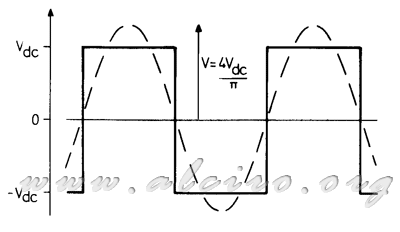
Figure 3.22. Waveform voltage in a phase of a hybrid excitation sequence operating with two active phases, showing the voltage fundamental component.
The fundamental component of the supply voltage has an amplitude of V = 4V dc / π, where Vdc is the DC voltage supply. The fundamental component of phase voltage can be written as:
\\ V_B\ =\ V*cos(\omega *t-\frac{2}{\pi })) (3.21)
(3.21)
instantaneous voltage and current for phase A is expressed by the equation.
+e_A) (3.22)
(3.22)
The fundamental component of current through phase A can be expressed as:
) (3.23)
(3.23)
where a is the phase angle. Substituting the fundamental voltage and current component in the equation 3.22 yields:
\ =\ R*I*cos(\omega *t-\sigma -a)-\omega *L*I*sin(\omega *t-\sigma -a)+\omega *\psi _M*cos(\omega *t-\sigma )) (3.24)
(3.24)
The vector diagram for this equation can be seen in Figure 3.23.

Figure 3.23. Diagram of vectors with the components of a phase for a hybrid engine.
In the vector diagram the voltage applied to the phase equals the sum value of induced stress and strain on the resistance and inductance. The tension in the resistance is in phase with the current while the voltage in the coil is offset to the current in π / 2. The induced voltage leads the current by the stage at an angle to and is delayed to the voltage applied at an angle δ. In this vector diagram takes into account only the fundamental current, although this is formed by a series of higher frequency harmonics, they do not contribute to the torque produced by the motor.


