1. MOTOR STEP BY STEP (STEP MOTOR)
The stepper motor (step motor) is designed for accurate positioning and discreetly, with its axis angular increments, called steps. These are produced in reversing the current through the windings, which in turn is controlled by a solid state switches power. To them it sends a signal from discrete digital control circuit, which determines the action of the motor.
There are a variety of stepper motors, differentiated by their constitution and form of construction. Among these are three types:
- Permanent magnet motors.
- Variable reluctance motors.
- Hybrid engines.
1.1. Permanent magnet motors
This type of engines is characterized by the use of a cylindrical ceramic permanent magnet rotor. The magnet is magnetized radially in a series of poles. The stator consists of layers of ferromagnetic material, winding with the same number of poles than the rotor.
The pitch of this engine depends on the number of poles in the stator and rotor. Due to the characteristics of the magnetic material used in the construction of the rotor, the number of poles of this is limited, so the angles are achieved with this engine are great.
In an attempt to reduce the step angle can increase the diameter of the rotor magnet, that we thereby increase the number of poles, but also the moment of inertia of this (for a cylinder increases with the fourth power of diameter) . This dramatically reduces starting torque, so this possibility is ruled out. The adopted solution is to build the engine with more than one stator, which is available step angles less than 3.75 º.

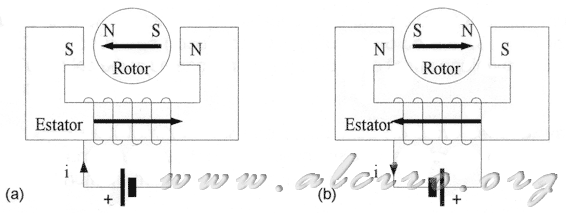
Figure 2.1 Two-pole motor and a phase
Figure 2.1 represents a basic permanent magnet motor with a winding (phase) and two poles. Figure 2.1 (a), the power of winding generates a magnetic flux in a clockwise direction, this is closed over the poles of the stator, causing the movement of the rotor, to achieve balance in the direction of magnetic fields to sleep . Figure 2.1 (b) changes the direction of flow, which leads to the reversal of magnetic flux, and therefore, the poles that were once attracted in balance now repel each other, producing a new rotor motion, seeking new orientation of the field, balanced position.
The result is a driving force in steps of 180 º. Generally speaking, the number of steps for the motor is determined by the expression:
n = n e * n p
Where;
n e = number of windings (phases)
n p = number of poles
by phase angle is:
Θ = 360 / n

Figure 2.2 Example of a 6-pole winding
A system with a number of poles greater than two could be the one shown in Figure 2.2. A winding (phase) with six poles for both the rotor to the stator. All poles are distributed equidistantly in a circle.
An engine consists of a single phase is meaningless, since the start address would be indeterminate, and the reversal would be impossible. The minimum number of stages is two.

Figure 2.3 Stepper motor two poles and two phases
With a two-stage motor and two poles per phase (Figure 2.3), you can control the direction of rotation. Figure 2.3 (a) shows the initial state, the two phases are excited a magnetic field that orients the rotor to a position of equilibrium. Figure 2.3 (b) the investment is made current in phase B, which produces a magnetic field variation clockwise turn, the rotor moves in the same direction, always seeking equilibrium position . Figure 2.3 (c) shows a new investment of the current in phase A, producing a new step of 90 ° clockwise.
Reversing the order of the current investment by stages, the movement also is reversed, resulting in a rotation of the rotor counter clockwise.


