4.3. Power amplifiers (Drivers)
Represent the link between the control logic signals and power signals, current through the windings. They have to respond quickly to stimuli, and provide the necessary current to the operating voltage required for feeding. Represent the power switches according to the control switch, formed by bipolar transistors, MOSFETS ...
4.3.1. Problems with Drivers
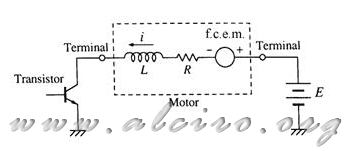
The winding of the stepper motor is inductive and appears in combination of inductance and series resistance. When the engine runs we find an electro motive force produced in the winding. The equivalent circuit for a coil represents the combination of all three series, as shown in Figure 4.23.
Power amplifiers that control the windings are subjected to the effects of pending and current surge produced by the inductive load, so it is necessary the use of suppressors to prevent damage to the power components.

Figure 4.23. Equivalent circuit of a winding of a stepper motor.
Motor parameters are subject to variations according to manufacturing tolerances plus those produced by the operating conditions. The design of the engine is designed to maximize output with minimal size. The motor body temperature can reach values around 100 º. Under these conditions the winding resistance increases by 20 to 25 percent.
4.3.1.1. Suppression circuits
When the transistor in Figure 4.23. is disabled, a high voltage is induced in the coil as a function of L (di / dt). This voltage is applied to the transistor, which may damage it. There are several methods to suppress the peak voltage and protect the transistor, are:

Figure 4.24. Suppressor circuits of a stepper motor (a) suppressor diode, (b) diode-resistant suppressors, (c)
(1) diode suppressor. If a diode is placed parallel to the winding, with the polarity as shown in Figure 4.24. (A), the flow of current flowing through it when the transistor is off, and the current decays at this time. In this scheme is hardly produced any change in current-law is carried out off, and the collector voltage of transistor is the voltage E, plus the voltage drop across the diode. This method is very simple, but on the other hand, the current flow shows a considerable slowness in time, producing a pair of delay.
(2) more resistance diode suppressor. The resistor is connected in series with the diode, as shown in Figure 4.24. (B), for rapid recirculation of the stream. VCE stress applied to the collector when it is off is:
 (4.2)
(4.2)
where
E = Supply voltage
I = current strike just before the
R S = resistance suppressor
V D = voltage drop across the diode
RS strength is required to produce a high current rapid decline, but this causes a potential drop in the collector high V CE. In this case the RS resistance value is subject to the maximum applicable voltage characteristics of the collector of the transistor.

Figure 4.25. Comparison of the effects of different types of suppressors.
(3) Zener diode suppressor. The zener diode is connected in series with the normal diode, as shown in Figure 4.24. (C). Compared with the previous cases, in this scheme the current decays faster when the transistor is turned off (see Figure 4.25.). The improvement of this method is that the potential applied to the collector of transistor is the supply voltage plus the zener voltage, regardless of the current. This is determined by the characteristics of maximum voltage applicable to the collector of the transistor.
Figure 4.26. shows a unipolar power supply circuit for a two-phase motor with double coil, with suppression by zener diode. The resistors R1 and R2 are to increase the slope of the current activation, see paragraph 4.3.2.1. (Additional resistance breeding.)

Figure 4.26. Example of a unipolar control a stepper motor with dual windings and Zener diode suppressor circuit.


