4.3.4.2. Chopper phase and inhibition

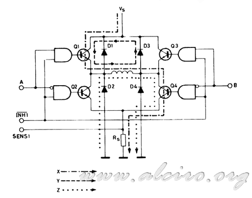
Figure 4.36. Evolution of the conduction current and recirculation in a chopper on stage.
Figure 4.36. shows a typical driver H-bridge configuration, consisting of four bipolar transistors as power switches, the adaptation of control signals to the excitation levels of the transistors is symbolized by AND gates. Control lines indicated by the letters A, B and INI correspond to the controls excitation of each branch line and inhibition of four transistors respectively.
The chopper can operate with any phase lines (A, B) or inhibition lines INI1. Depending on the chopper so the results are different in circulation intensity. Based on these we will choose one or another type of control for a given engine model.

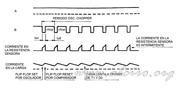
Figure 4.37. Waveforms and current control in a chopper on stage.
The chopper for phase begins with the commutation of the winding, for example by placing the line A and B high to low (Figure 4.36), the current flowing through the transistor Q1, through the winding, the transistor Q4 and Rs by the resistance sensor (line X in Figure 4.36.). When the voltage drop in sensor resistance Rs reaches the reference voltage Vref, the chopper located the line B at high level to switch the winding. The energy stored in the winding is dissipated by the recycle stream through Q1 and D3 (online and in Figure 4.36.). The current decays slowly due to the applied voltage is low (Vce sat.Q1 + V D3). Another way to make the chopper per phase is acting on the line A instead of B, put the line to a low level, this causes the recirculating flow is established through transistor Q4 and diode D2, circulating Rs (Z line in Figure 4.36.). In this system the current decays a little faster as the voltage across the winding is higher (Vsat Q4 + V D2 + V rs). But the resistance Rs is affected in an increase in power, and therefore in size and price.
Figure 4.37. can observe the waveforms of signals involved in the chopper on stage. Line A is consistently high, while the switching is done by line B, resulting in recirculation at the top of the bridge. Depending on the switching period of the line B, we have the intensity in the sensor resistance. The current through the coil is shown in the last position. In this we can see that the decay proceeds more slowly than in activation.

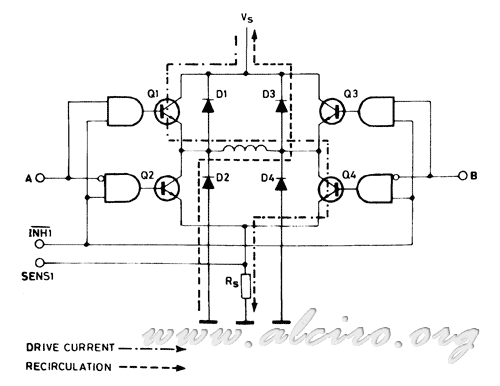
Figure 4.38. Evolution of the conduction current and recirculation in a chopper for inhibition.
The alternative to this type of control is to activate the chopper acting on the lines of INI1 inhibition. For example, if the line is level A and B high-low, Q1 and Q4 are conducting. The current flowing through the transistor Q1, winding, the transistor T4 and the sensor resistance Rs (dashed line in Figure 4.38.). In this case, when the voltage across Rs reaches the reference voltage Vref, the control line active response inhibition INI1 (puts low). INI1 all transistors off, leaving the outdoor coil. Then the current flows to ground through diode D2 and through diode D3 to positive. The energy stored in the coil is discharged on food. Now the tension is applied to the winding is the voltage, which typically has a high value, so the current decays rapidly.
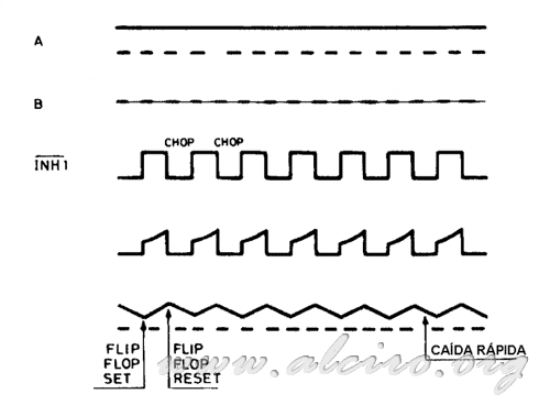
Figure 4.39. signals can be observed for this type of control. This shows the signal line switching INI1 performing as well as the current through the coil, noticing a rolloff greater than that shown in Figure 4.37. for the control phase.

Figure 4.37. Waveforms and control the current in a chopper for inhibition.
The bridge control is not suited to power variable reluctance motors, as they do not require reversal of the current, but is very effective hybrid motors and permanent magnet.
By inhibiting the chopper can be used to control unipolar motors, due to the high inductance coil has twice. To these he favors the rapid fall of the current of this type of control. While the control is more appropriate phase bipolar motors to power in these inductance is lower. However, you can opt for either of the two systems to control the motors.


