4.3.3. Stepper motor control for power
As noted in the previous section, the supply voltage winding plays an important role when working at high speeds. Be selected supply voltage as high as possible, providing an increase in the rate of change of current. The adoption of a constant current generator limits the intensity of the phase, and is only active when the current through the coil reaches its nominal value. Before reaching this value, the current generator is saturated and the voltage is applied directly to the wound.
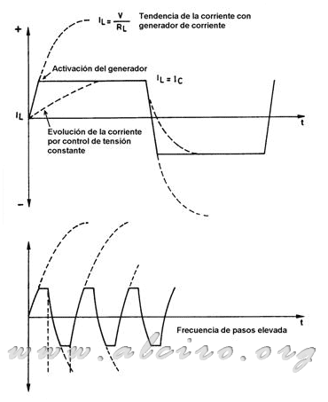
Figure 4.30. Waveforms of current through the winding with a power generator.
Figure 4.30. can observe the evolution of current through the winding. This tends to assume the value marked by the supply voltage (V / Ri), but when it reaches the nominal value Inom activates the power generator, limiting the increase in this level. From this we can deduce that increasing the power supply voltage increases the value it tends, but as the cut is always Inom level, the effect is that the increase from zero to this value proceeds more rapidly. You can also see the difference between the evolution of current with constant voltage control and generator. Working at high ratios of steps with this system, the current reaches its nominal value (Figure 4.30.), Which was not the case with voltage control. The loss of the nominal value of current is produced at higher speeds.
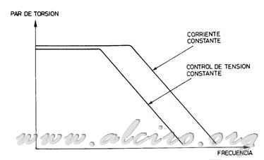
Figure 4.31. Comparison of the characteristics of torque / speed control voltage and current control.
Figure 4.31. shows the relationship between the pair and the typical speed of a stepper motor. The improvement in the flow of current work at high speeds provides more engine power, and consequently an increase of available torque to the relationship of steps, where normally it is more necessary.
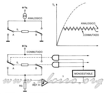
Figure 4.32. Control bipolar bipolar analog and switched-current control.
The current generator combined with the high voltage ensures that the rate of change of current through the coil is fast enough. However, in a static low speed, causes the loss of power in the current generator to increase dramatically. Therefore system performance is extremely poor. The remedy is the adoption of a switched power regulator.
Figure 4.32. shows the control of a bipolar winding form, the first with analog current generator and the second switched control, you can also see a comparison in the form and evolution of current through the winding to the typical responses of both regulators.
In the control switch, the phase winding is connected to the supply voltage until the current sensed at the ends of RS reaches the desired nominal value set by the reference voltage. At the time of switching, the switch terminal that was previously connected to + VS, changes position and shorted winding. Thus, the current flowing through the winding (highly inductive) lapsed at the close of the terminals of the winding on themselves. The fall time of this current during this phase is determined by a monostable circuit or oscillator pulse. After this time, the switch returns to its original position, re-connect to + VS, which starts a new charging by induction, starting a new cycle.
As the only losses with this technique are the switching element saturation and the winding resistances, the overall performance of the whole is very high. The average current flowing through the power line is less than the current through the coil due to reversal of the circuit.
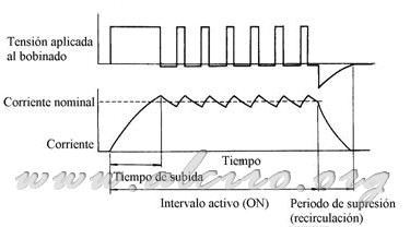
Figure 4.33. Waveforms of voltage and current in the switched control.
The power supply must be capable of providing rated current for both phases. But when the current through these windings has reached the nominal value, starts working the switch (Fig. 4.33.) Connecting and disconnecting the coil to the source, resulting in reduced power consumption. The average intensity consumed is well below the nominal flowing through the coil, is directly dependent on the supply voltage, so that more tension, less than average intensity. In this type of control the ratio, power, the power supply source equals less engine power loss, which can be neglected, (VA * IA = VM * IM). But tensions in this equality are very different, while the engine needs to operate low voltage, about 5V, the source can reach or even surpass 100V. Thus, to ensure compliance with equality, the intensity of the source has to be well below the engine. Thus, the power supply is subject to lower loads. This control of phase current must be carried out separately for each motor phase to obtain the best possible relationship between the electrical energy consumed and the mechanical energy supplied.
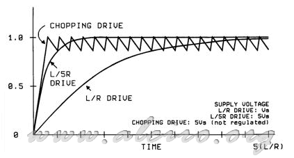
Figure 4.34. Evolution of current through the load for the different feeding techniques.
Figure 4.34. A comparison in the current response of the different types of control. Tension Control L / R, control strain with additional resistance by L / (5 * R) and the switched control.


