4.3.4. Bipolar chopper control in H-bridge
The excellent characteristics in terms of torque / engine size on unipolar bipolar, has relegated the latter almost to extinction, especially with the emergence of specific integrated bipolar control, with a ratio of very low prices and offering control and ease of assembly similar to that of the unipolar. Hence, in most applications is adopted by a bridge control switched bipolar H.
4.3.4.1. H-bridge for a two-phase motor.

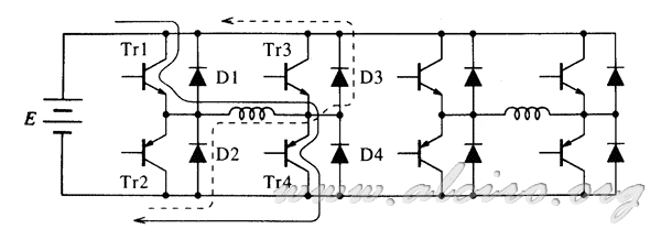
Figure 4.35. Bridge circuit for bipolar control of a hybrid of two phases.
In the two-phase hybrid motors, the bipolar driver gives excellent results for the following reason, all the windings are always excited. Compared with unipolar driver, in this current flows in a winding direction, being able to obtain an increase in torque from 20 to 35%. In the two-phase hybrid motors, the bipolar driver gives excellent results for following reason, all the windings are always excited. Compared with unipolar driver, in this current flows in a winding direction, being able to obtain an increase in torque from 20 to 35%.
Engines must have four terminals to operate according to the scheme of Figure 4.35, the engines with a number of different threads to four, can be used if two-phase control and support the bipolar see paragraph 4.2.2 (engines 8-wire). The bridge driver has to take special care in the activation of power transistors, as they may be damaged and this can occur if the two transistors are in cascade are activated simultaneously. When a transistor is switched off, you have to give a time frame before the other transistor is switched on, as both short-circuited transistors rotted. This is because normally the downtime is greater than the activation time, so that if one connects and disconnects the other at the same time, a short circuit. They have to take appropriate security measures to prevent this from happening.
Parallel-connected diodes of the transistors are to suppress the voltage spike that occurs when the transistor is turned off. If Tr1 and TR4 are driving, current follows the path shown in solid line in Figure 4.35. Just after the transistors Tr1 and TR4 is blocked, the current through the winding closes D2 and D3 circulating on the power supply. In terms of energy, magnetic energy present in the winding is fed to the power supply. The bipolar driver, the magnetic energy is lost when you close the loop on the winding, the diode and the external resistance. The bipolar driver bridge configuration to unipolar leads in this regard.
Playing with the driving control and blocking of the transistors, you can get different paths recirculation current. Depending on each of these different characteristics are obtained that make them more or less appropriate for a particular application.


