6. STAGE OF POWER AND CONTROL CIRCUIT
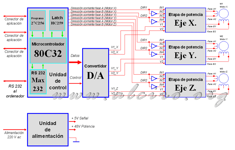
The application is designed for use in a jig with three axes Cartesian robot or an X, Y and Z. This will have a control board, whose block diagram shown in Figure 6.1.
From a personal computer PC, and through RS232 line, transmit the control codes, codes developed specifically for this application, such as speed, acceleration and motor current, or other as the positions of the X, Y or Z, etc.. These are collected by the microprocessor (main element of control) and transformed into signals activating the power drivers, and analog signals processed by the A / D to generate the microstep. There are three stages of power flow control, for each to power the motor for axis X, Y and Z. Finally, the essential element, the power supply that provides power to run the circuit, it delivers two voltages, one for signal and control, 5 V, and the other power (engine power) , 48 V.

Figure 6.1. General block diagram of a board of control of three stepping motors


