2.1.2. Static position error
In many applications we can find a position error due to mechanical loading, ie the motor shaft can be seen under an external torque produced by the mechanical moves. Friction can overcome the torque produced by the engine and cause a small offset angle with respect to the position of passage in a state of equilibrium.

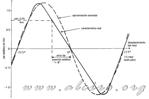
Figure 3.4. Deviation of static torque position of the static torque characteristic curve.
For example, Figure 3.4 shows the characteristics of an engine with 8 teeth on the rotor and a peak torque of 1.2 Nm at rated current. When the load torque is 0.75 Nm, the motor moves about eight degrees from the position of step (equilibrium), until the developed torque is matched to the load.
An estimate of the static position error can be obtained if the property (static torque / rotor position) is close to a sinusoid. For an engine with teeth on the rotor d and a peak torque T p to a shift Θ of the step position (balance), the torque developed by the motor is approximately:
) (3.1)
(3.1)
When the load torque T l is applied to the rotor, it moves to a new position at an angle Θ m, in which the motor torque and load are equal:
) (3.2)
(3.2)
and static positioning error is:
}{d}) (3.3)
(3.3)
The mistake made in the approximation grows as we move from the position of the step, until you reach the maximum torque. From this, the error is smaller.
Another way to get the static position error is to approximate the slope of the curve to a line.


