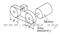
5.1.5.3. Moving objects using tape
 (5.31)
where
J1 = pulley inertia (kg * m 2)
D = diameter of the pulley (m)
M = mass of the object and tape (Kg)

Figure 5.12. The movement of objects using tape.
5.1.5.4. Linear motion by worm and gear
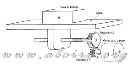
When the piece and the work table are moved by auger as shown in Figure 5.13, the inertia of the rotor assembly is reflected in:
*(\frac{N_{1}}{N_{2}})^2+M*(\frac{p}{2*\pi})^2*(\frac{N_{1}}{N_{2}})^2) (5.32)
(5.32)
where
J1 = gear inertia coupled to the motor (kg * m 2)
J2 = inertia of the gear attached to the worm shaft (Kg * m 2)
J3 = screw inertia (Kg * m 2)
N1 = number of gear teeth attached to the motor
N2 = number of gear teeth attached to the worm
M = mass of the workpiece and the table (Kg)
p = pitch of screw threads (m)

Figure 5.12. Linear motion of a mass and workpiece by spindle and gears.
Transformation of force:
)
where
T = equivalent motor torque (N * m)
F = work force of friction force (N)
In a system with direct coupling of the motor shaft to the screw, the coefficients N 1 / N 2 are removed from the equations.


