5.2.2. Theory of linear acceleration pulse intervals
To start discussing the linear acceleration has to leave for granted two condición:
1.-The stepper motor under the conditions laid down is capable of starting and stopping at the rate of pulses f 1.
2-Engine can accelerate to β 2 until the final reason for steps of f s s.
Initial conditions (boot) relate to the characteristics of pull-in and the following (acceleration, displacement and slowdown) to the pull-out. It can now introduce the concept of continuous variation of steps f reason:
 (5.50)
This is illustrated in Figure 5.25 by a solid thick line. This line represents the speed of motor control, but the actual speed profile is similar to that shown by the line dotted in the same figure. The time from each pulse is indicated by,
 (5.51)
< br / > then the angle rotational for each period of discrete pulse to pulse (m-1) is a pitch, the area of each trapezoid A, B, C, D... amounts to a step, for example; if f = 10 pas/s corresponding to the height of the rectangle and t = 0.1 s that represents the base, then the area is the product of the base altitude 10 pas/s * 0.1 s = 1 step.
Pulse interval can now be defined Δ t m as
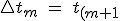}-t_m "Intervalo de pulsos") (5.52)
(5.52)
and the representative frequency pulse or reason for steps fm for the period Δ t m is defined as.
 (5.53)
this value is identical to the value of the 5.50 equation, then the time t = t m + Δ t m / 2 at the midpoint of each interval

Figure 5.25. Time of pulses in the linear acceleration.


