5.1.7. Friction, torque and inertia
Any mechanical system optimized for good and it always has a friction in all moving elements experiencing either linear or rotary, this translates into a loss of torque obtained from the engine torque delivery. In some cases this friction is important enough to take it into consideration.

Figure 5.16 Typical elements displayed on a linear positioning system.
Figure 5.16 shows an example of linear positioning system using linear guides with ball runners for the sliding of the load, and a spindle (screw) with a ball nut for transmitting motion from the engine. The spindle attachment is made by bearings, can be of two types, with and without preload, the first friction is negligible, and the second directed by the manufacturer. The spindle nut may also be preloaded or not the game to avoid travel. The equivalent torque depends on the preload F P, the ratio of pre K and p leadscrew pitch.

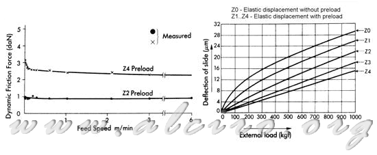
Figure 5.17 Characteristics friction / speed and deformation / force of the roller ball.
In the load has to take into account the friction with the roller ball. This equivalent force is determined by the mass of the system M (load + media) and the coefficient of friction μ, giving a force F = μ * M. This force can be neglected if the skates are not preload or weight M is small.
*p}{2*\pi*\eta})*\frac{N_1}{N_2}) (5.36)
(5.36)
Figure 5.17 shows the friction as a function of deformation speed and load function for linear guides skates.

Figure 5.18 Inertia of different mobile element linear positioning system.
When taking into account all elements involved in the system shown in Figure 5.18, Equation 5.32 becomes:
*(\frac{N_1}{N_2})^2+M*(\frac{P}{2*\pi})^2*(\frac{N_1}{N_2})^2) (5.37)
(5.37)
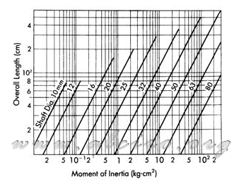
In this we have the inertia of the motor rotor J M and J 1 the first gear is connected directly to the motor shaft. On the other side are the inertia at the other end of the gear, which must be processed by applying the ratio of teeth (N 1 / N 2) 2. J2 represents the inertia of the second gear, J A of the coupling between J H axis and the inertia that has the spindle. In last place is the derivative of the load mass plus the mass of the table and elements of movement, it has to transform a first translation movement to a rotation by applying the ratio [P / (2 * π )] 2 and second gear ratio. If the transfer is made directly between the motor shaft and the spindle without using gears, the ratio (N 1 / N 2) 2 is removed from the equation 5.37, the inertia of the spindle can be obtained directly from the curves that provides the manufacturer (see Figure 5.15) or apply the following equation for cylindrical elements:
 (5.38)
where
J = moment of inertia for a cylinder (kg * m)
ρ = density of material (steel 7.8 * 103 kg / m 3)
D = diameter of the cylinder (m)
L = length of the cylinder body (m)

Figure 5.19 Moment of inertia of the screw diameter based laminates.
Retrieved torque and the equivalent inertia is applied to Equation 5.1 to obtain the necessary motor torque.


