6.1. Amplifier
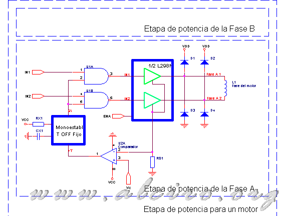
The power stage is the element that converts the signals and voltages, which provides the microprocessor and the A / D, intensity variations in the windings of the motors. Within this block, you can distinguish the parts for the driver, comparator, monostable and control signals for the type of chopper. The application has three stages of power to control exactly the same three engines. The study was performed to one of them, being able to extrapolate the results for the remaining two.

Figure 6.2. Block diagram of the power amplifier to control a stepper motor
6.1.1. Driver
When choosing the power driver has chosen to select the integrated home L298N SGS, it is perfectly suited to the needs of the application and meets the minimum requirements as an affordable and readily available on the market.
The circuit consists of two bridges in H formed by bipolar transistors, which can control two windings, and therefore a hybrid of two phases (see figure 6.3). Inside, the doors to attack the base of the transistors from the input lines form the control circuit and adjusting levels, moving from 5 V logic level power level of the bridge. entries consist of three basic lines:
- Inputs In1 and In2 (in3 and In4 for element 2) for the activation levels of the transistors for each branch of the bridge. A logic level 1 (5V) makes driving the upper pole and a level of 0 does the same with the bottom.
- The entry of inhibition EnA (ENB for element 2) blocks the control inputs and therefore places the 4 bipolar bridge in a state of blockade.
The line for the mass level bridge will be reflected on the outside independently using pins 1 and 15, allowing placement sensor resistance to determine the flow of current through the motor winding.
The integrator provides a maximum continuous current of 2A and allows a supply voltage of 50V. This bipolar motors can control up to two amps per phase, and enables the control current with a relatively high upslope due to the high power potential. Resulting in a good frequency response. Is encapsulated in a 15-pin multiwatt with a dissipation of 25W. Perhaps the only negative factor is the absence of recirculation diodes, so that they are to be placed on the outside, making the design of the plate.


