5.1.8. Example of calculating the torque in linear system
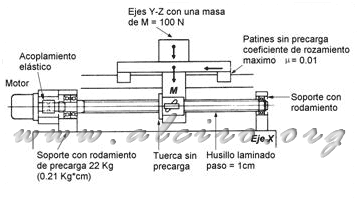
Example 1. Find the engine torque required to operate the system shown in Figure 5.20, which represents the X axis of a Cartesian XYZ positioning system. The operation is performed with a motor of 1.8 ° per step, linked by a coupling of aluminum directly to a spindle, with a pitch of 10 mm. The subject is formed by a support bearing preload of 22 kg, on the other end has a bearing without preload. The guide element comprises a linear guide 20 mm, with ball bearings skate without preload. The mass of all elements of YZ axis flat on the X axis is 10 Kg workforce needed to drive the cutting tool is 200 N. The maximum acceleration is 0.5 m / s 2.

Figure 5.20. X axis linear positioning system XYZ.
Other information:
J motor = 150 g * cm 2
Screw L = 0.5 m
μ = 0.01
The torque required to operate the system is partitioned into first place in the starting torque to preload the bearings. The manufacturer indicates that support for a 12 mm shaft and a bearing preload of 22 kg starting torque is 20.59 N * m * 10-3
Fc force necessary to move the load with a coefficient of friction between shoe and guide is μ = 0.01 μ * M (rolling resistance) which along with the labor force F
 (5.39)
Rolling resistance is negligible, since the echo of using ball and roller guides provides a very low coefficient of friction, this is added the light weight of the system. Transforming the force to a pair with a 10 mm pitch screw and a yield of 90%.
 (5.40)
The spindle nut is not preload, so wide losses they are considered negligible. Total motor torque required to move the load or move at constant speed is:
 (5.41)
If the system is accelerated, it has to perform an analysis of the inertia. Of a spindle of 0.5 m in length and a diameter of 16 mm,
 (5.42)
you can also get the moment of inertia from the graph in Figure 5.19, the intersection between the length of 50 cm and diameter 16 mm spindle, giving 0.25 Kg * cm 2. Inertia coupling between the rotor shaft and the spindle can be neglected as it is aluminum and does not represent an appreciable increase. The inertia resulting from the load is determined by the expression:
^2\ =\ 10*\left( \frac{0.01}{2*\pi} \right)^2\ =\ 2.533*10^{-5}\ Kg*m^2) (5.43)
(5.43)
if the motor rotor inertia is 150 gm * cm 2, the total inertia of the system is.
 (5.44)
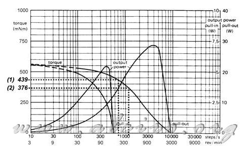
Applying Equation 5.1 for a linear acceleration of the load of 0.5 m * s-2 (the engine accelerates to 100 * Π radians / s 2), we obtain the motor torque and speed required to remove the system.
 (5.45)

Figure 5.21. Caracteisticas curves of a hybrid engine from 1.8 º to the situation of torque needed to accelerate to 50 cm/s2 sistena (1), and the constant speed (2).
If you place the pair obtained to accelerate the shaft on the torque characteristics / speed shown in Figure 5.21, you get the steps right up to 700 steps / s that can reach the engine to maintain this situation. Placing on the same graph the torque at constant speed we get a ratio of 1100 steps steps / s for this state.


