4.2.2. Stepper Motors 8-wire
Depending on the type of connection, the power stage can be of two types: unipolar or bipolar. In the unipolar windings are energized one at a time, while in bipolar pairs is performed by current reversal. Control is the same as mentioned above for the motors 4 and 6 threads.
The connections and the relationship of colors typical for an 8-wire motor in bipolar and unipolar connection illustrated in Figure 4.18.

Figure 4.18. Possible connections with a hybrid stepper motor eight threads.

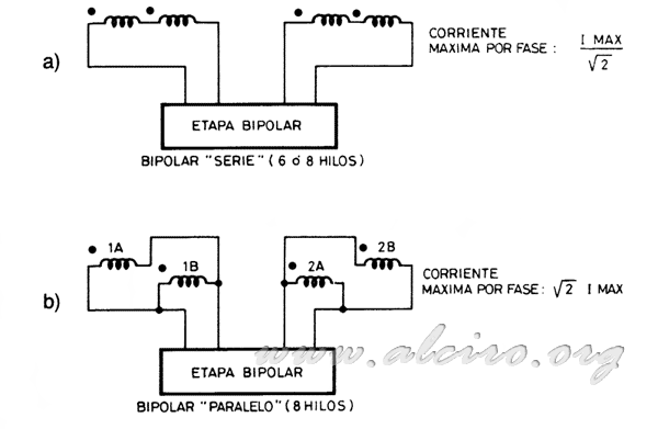
Figure 4.19. Stage bipolar series connection of 6 or 8 wire and 8-wire parallel.
Figure 4.19. shows that with a bipolar output stage there are basically two possible connections (actually four), connecting the windings in series and in parallel. The latter allows for top pair with a wider range of speeds, but the resulting increase in consumption, as current per phase is doubled relative to the serial connection.

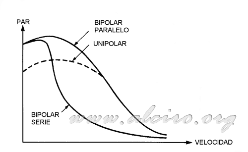
Figure 4.20. Relationship between torque and speed for different types of food with the same engine size and the maximum current available in each case
The type of connection will depend on the speed and torque requirements of the application. In the unipolar configuration results in increased engine performance at high speed, bipolar does at low speeds. Looking at the curves torque / speed shown in Figure 4.20. shows that the response of unipolar connection is fairly uniform, reaching a regime of high steps without decay par. While in the bipolar configuration yields a higher torque at low speeds, but it decays rapidly. In other words, if we use the bipolar connection to haul a load with the pair that provides the operating speed can not increase much, as soon exceed the load torque at the motor. This effect is heightened even more in the series connection, which provides high torque but low speed regime. However with the unipolar connection with a load close to the pair that provides the engine for this type of connection makes it to work at higher speed, the torque remains constant up to a high regime.

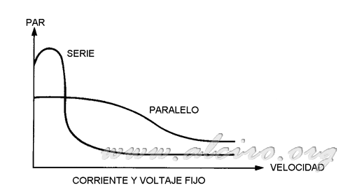
Figure 4.21. Response torque / speed connections in series and in parallel to a fixed voltage and current.
So far we have only considered the theoretical maximum available engine torque, assuming that the only limitations are the dimensions of the engine and the working temperature, always at the maximum power available for each case (conditions for obtaining the curves Figure 4.20.). When characteristics are compared on the basis of a fixed-phase current. The torque at low speed in the serial mode can be almost double that of the parallel mode, as shown in Figure 4.21. It should be noted that under these conditions the engine will heat much more at low speeds in the serial mode, because the phase current is flowing through a double number of turns of winding. Moreover, doubling the number of turns brings an increase in the inductance of the windings. That in practice means that the current fall more rapidly with increasing speed. The actual percentage of the increase in torque in the series about the parallel mode will depend on how close you are to the core saturation in these conditions.

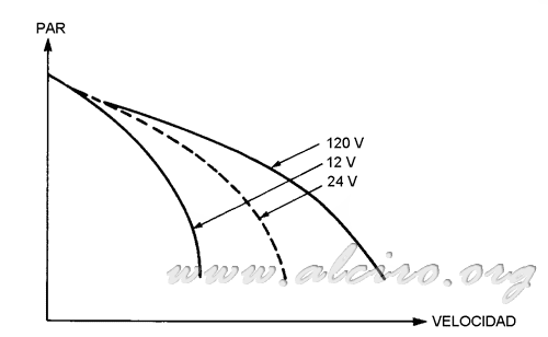
Figure 4.22. Relationship between torque and speed for different values of supply voltage.
The engine choice has to take into account the type to be used, especially in the series connection, since the switching time of the windings is affected by the time constant L / R. If using an engine with high inductance and low winding resistance, this time increases and the consequent limitation of reason steps per second.
One way to increase torque at a given speed range or whatever it is, increase the speed range for a given pair is to use power amplifiers that support higher voltage. The adoption of a voltage causes the upslope in the current through the windings faster, achieving a better flow of information when working at high speed. Figure 4.22. shows the responses of torque / speed according to different supply voltages.
Another aspect to take care when connecting an 8-wire motor is to monitor the correct phase of the windings, because if they are connected in opposition, the effective inductance would be virtually zero and could damage the amplifier.
When it comes to the choice of engine, if you have bounded the needs of the application can choose the bipolar or unipolar, 4 and 6 wires respectively, as needed. But the most versatile is to have 8 wires, as this allows any type of connection.


