4. ENGINE POWER STEP BY STEP
4.1. Excitation sequences
Controlling a stepper motor is achieved by feeding the different phases in a current. Depending on the level of intensity, polarity and the sequential order of excitement we get different answers on the engine. These different ways of feeding the engine are called (sequences or excitation power).
In this section we will refer mainly to the excitation of hybrid engines, which are the most widespread. Keep in mind that the control of variable reluctance motors differs from other hybrid and permanent magnet that only have a sense of power to drive the winding.
4.1.1. Sequence of two active phases (full step)
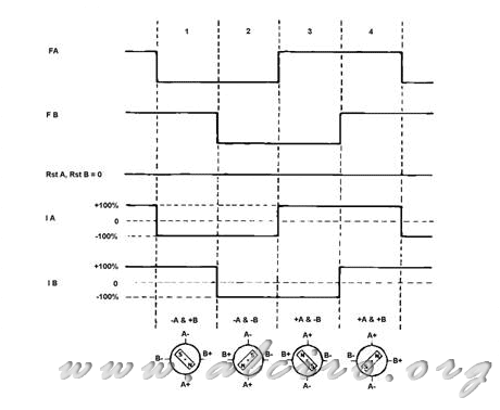
This sequence is characterized by two phases are always enabled. The movement of the rotor is achieved by changing the polarity in the current flowing through the windings of the phases. Reversing the direction of rotation corresponds to the reversal of the excitation sequence, for example, if the sequence to obtain the incremental movement of a step is + A + B-A + B,-AB, + AB, + A + B, ... movement in the direction of advancement could get moving in the right sequence, and reverse the direction of rotation has to reverse the sequence, ie towards the left from the last position. Table 4.1 shows the sequence of excitation of two active phases (full step).
Table 4.1. Sequence of two active phases (full step).
| Clock | Steps | Phase A | Phase B |
| Ref | Ref | - I | + I |
| 1 | 1 | - I | - I |
| 2 | 2 | + I | - I |
| 3 | 3 | + I | + I |
| 4 | 4 | - I | + I |
The pair obtained in this sequence is the maximum that can deliver the engine, and at all times both phases are active with rated working. The equilibrium position of the rotor is established between the stator teeth for each phase in equilibrium with the magnetic fields generated by each winding, see Figure 4.8 (b).

Figure 4.1 Sequence of development with two active phases

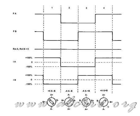
Figure 4.2 Sequence back with two active phases
In Figures 4.2 and 4.3 we can see the waveforms corresponding to the excitation sequence in full step forward and backward direction respectively. FA and FB waves under the direction of flow for each phase, is positive current level 1 and level 0 is negative. The signs of inhibition of current through the phase are represented by forms RstB RSTA and that for the full step sequence are zero, do not inhibit the current. The set of lines formed by FA, FB, RSTA and often RstB control lines typical power circuits (drivers) that feed the engine. The current through each phase is symbolized by the waveforms of IA and IB. Finally, the position of the rotor with this active phase is symbolized by a model of two-pole motor and two stages.


