2.2.3. Mechanical Resonance
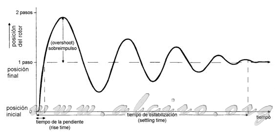
A stepper motor is asked to respond to angular displacements between the equilibrium position of the steps, based on changes in arousal. The system's response to a change in the arousal response is called a step, which is generally very oscillating. The typical response shown in Figure 3.12. In applications that require precise positioning this response has major disadvantages swing, for example, if a stepper motor is used to move the carriage of a printer and print a character, the work speed is limited by the time it takes to move the car precisely to the position of each character.

Figure 3.12. Typical response of a step of a stepper motor.
The parameters of the response of a simple step are defined in Figure 3.12. The slope time (rise time) is the time it takes for the motor to reach the position of the step, it determines the maximum speed we can achieve. The system has some overshoot (overshoot) to the desired position, with the amplitude expressed as a percentage of the total step. Finally settling time (settling time) is the time at which the overshoot falls to 5% of the amplitude of a step.

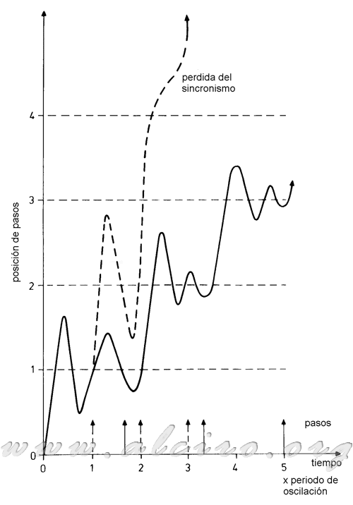
Figure 3.13. Responding to a ratio of steps near the resonance frequency.
---- Ratio = resonance frequency steps.
___ Because of steps = 0.6 * natural resonance frequency.
One consequence of the high fluctuations in the response of a step is the existence of resonance effects, at a rate of steps on the natural oscillation frequency of the rotor. Figure 3.13 shows two motor responses to a series of steps at a different frequency. In the first answer, the reason for passage is about a 0.6 time in the natural oscillation frequency, and therefore the rotor is below the equilibrium position and has a low speed when the next change occurs in the excitement. The rotor reacts with a uniform response to all steps. In the other response ratio steps is approximately equal to the natural oscillation frequency and the rotor is in the position of equilibrium with positive velocity at the end of the first step. As a result of this initial velocity, the response of the second step is oscillating rotor swings a lot about the new equilibrium position. The rotor oscillations increase in amplitude in successive steps that are executed, until eventually it loses its equilibrium position. The amplitude of oscillations exceeds the motor torque, causing the rotor to move toward some alternative way position, moving one (rotor tooth pitch) completed from the current position. The correspondence between the position of the rotor and the number of changes in the excitation is lost and therefore the rotor movement is erratic.

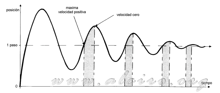
Figure 3.14. Regions of the response of a step susceptible to resonance.
Resonance regions with loss of the pair are defined by engine characteristics and are illustrated by (dips) on the curve (pull out) speed torque characteristics in Figure 3.8. These (dips) occur at the natural oscillation frequency for the response to a single impulse, but can also occur if the interval of excitation coincides with the rotor to move towards the equilibrium position with positive velocity. These regions are shown in Figure 3.14. The rotor passes these time intervals multiples of the oscillation period (1 / f n).
 (3.14)
If the natural oscillation frequency for a motor is located at around 100Hz, we would (dips) in the characteristic curve of torque / speed 100, 50, 33, 25, 20, ... steps per second. This result is not accurate, since the oscillation frequency depends on external actions and compensating charge.

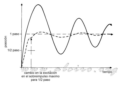
Figure 3.13. Reply with a half-step control medium.
___ Response to a full step excitation.
---- Response with half an intermediate step.
If step corresponds to the change of excitation of phase A to phase B, the middle step is achieved with both phases A and B excited. Figure 3.15 shows in dashed trace system overshoot for phases A and B excited. The rotor is moved by the effect of overshoot near the equilibrium position of the phase B (1 step). At this moment the excitation is switched only phase B (phase A blocks) and transition to the final step is achieved
with a small initial error, and consequently a small overshoot. The contrast between this response and that derived from the sequence of excitation of a single phase (continuous trace), is the practical nullification of the overshoot and as a result is obtained minimizing the effects of resonance. And a settling time (settling time) is extremely small compared with that obtained in response to a step. This system has a major drawback is that the time changes of excitation in the intermediate half-step control is critical and depends on the load conditions.


