1.2. Stepper motors, variable reluctance
The variable reluctance motor rotor consists of a non-magnetized ferromagnetic foil, forming a cylinder around the shaft, these are slotted lengthwise to form teeth (poles of the rotor). The grooving of the rotor leads to a reluctance variation depending on the angular position.
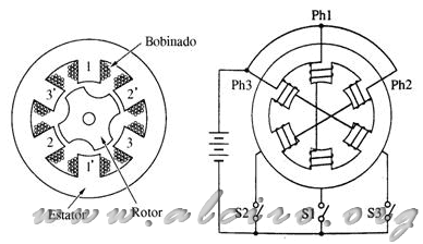
Figure 2.4 Section of a stepper motor three-phase VR
Also the rotor, the stator is formed by layers of unmagnetized ferromagnetic material, with a series of grooves longitudinally, which house the windings of the phases, forming the stator poles.
Usually the constitution of the rotor and stator is based on ferromagnetic films, but you can find drives with solid iron constitution sweet.
The number of rotor teeth is less than the number of stator teeth, so that only one pair of poles in the stator and corresponding rotor pole pair per phase can be aligned. Figure 2.4 represents a three phase VR motor with six stator poles and four rotor. Each phase has two coils located at opposite poles. Figure 2.4 (b) shows a connection of the coils in series, also being able to connect in parallel.
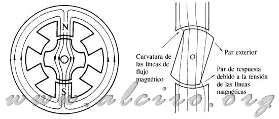
Figure 2.5. VR 4-pole motor. (A) position of equilibrium with one phase excited. (B) Curvature of the magnetic flux lines that create the pair.
Some circuit breakers are responsible for providing current to each phase. If S1 is in ON state, current flows through phase 1 and 1 ', generating a magnetic flux running through the stator and the poles are closed for stage 1 of the poles of the rotor. When the poles of the rotor and stator are aligned, we have the maximum flow, which corresponds to the minimum reluctance.
If the rotor moves away from the equilibrium position, as a result of external torque applied to the rotor, it responds with a pair in the opposite direction that opposes the motion, this results from the curvature experienced by the magnetic flux lines between the poles of the rotor and stator. Magnetic flux lines tend to be parallel to each other, and to move by the most permeable to find, when they are deformed, generating an attractive force on the elements that flow, trying to maintain balance. A sample of this is shown in Figure 2.5 (b).
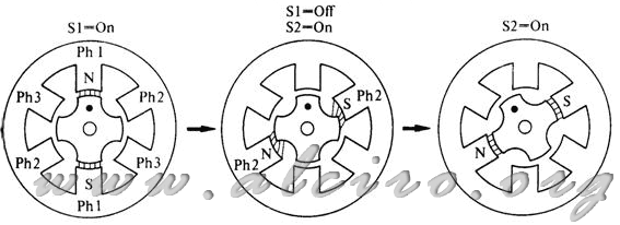
Figure 2.6. Step excitement produced in the switching stage of phase 1 to phase 2

Figure 2.7. Form of the steps and sequence switching of a VR motor three-phase variable reluctance
Starting from the equilibrium position with stage 1 on (Figure 2.6 (a)). One step is obtained by placing a state of phase 1 and phase 2 OFF to ON state, in this moment of rotor poles closer to the poles of the stator phase two, are drawn in an attempt to circulate the magnetic flux lines (Figure 2.6 (b)), producing a rotational movement between the two poles to be aligned (Figure 2.6 (c)). With this operation we obtain a rotor pitch.
Figure 2.7 shows the sequence of progress in a counterclockwise VR four-pole motor, the result of the activation sequence (Ph1-Ph2-Ph3-Ph1..) Stator phase.
The number of steps for these motors are calculated the same way as in permanent magnet motors, formulas (1) and (2).
Taking the motor of Figure 2.7, we have four poles in the stator and rotor three phases, therefore the number of steps per revolution of the rotor is 3 * 4 = 12. The step angle is 360 º / 12 = 30 º.
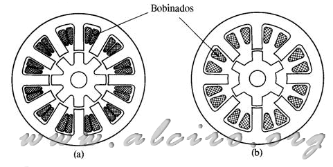
Figure 2.8. Part of a VR motor 15 degree pitch.
(A) three-phase motor: stator pole number = 12, number of rotor poles = 8.
(B) four-phase Motor: number of poles in the stator = 8, number of poles on the rotor = 6.
For a given pitch, you can choose different combinations, playing with the number of phases. Figure 2.8 shows two motors with step angles of 15 degrees, the first three phases in the stator and eight poles in the rotor, the second of four phases in the stator and eight poles in the rotor.
So far, all engines that have been treated with large pitch angle. For small pitch angles, all you have to do is increase the number of poles (teeth) of rotor (Figure 2.9). The stator configuration remains the same, it keeps the number of phases, but the poles are scored on several teeth, for comparison with the rotor poles are aligned.
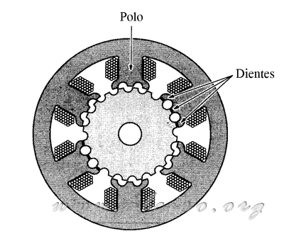
Figure 2.9. A section of a three phase VR motor, two windings per phase and three teeth per pole in the stator, the number of teeth on the rotor is 20 and the step angle is 6 º.
Figure 2.10 shows a linear distribution of the poles of the rotor and stator, representing the magnetic flux and displacement in one step.
A motor with small angles 1.8 ° and a large number of steps 200, as shown in Figure 2.11. The rotor has 50 teeth. The stator has 8 poles windings 8 scored on 5 teeth. The number of phases may be four, joining the windings 1-5 (phase 1), 2-6 (phase 2), 3-7 (stage 3), 4-8 (phase 4). But also be performed in two phases, linking the windings 1-2-5-7 (phase 1) and 2-4-6-8 (phase 2), in which case the number of steps would be lower (100) and teeth of the stator poles for the same phase, are confronted with the rotor.
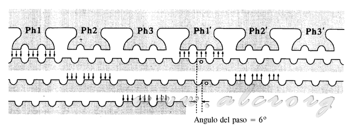
Figure 2.10. Linear model of stepping motor of variable reluctance.
A sample of such small dimensions that can be achieved in this engine illustrated in Figure 2.12, this is due to not having permanent magnet rotor can be minimized, resulting in very small diameter motors.
A second effect in reducing the rotor diameter is decreased moment of inertia of the latter. When you have a low load, this engine offers a very high turn ratio.

Figure 2.11. Section of a VR stepper motor of four phases, the number of teeth on the rotor is 50, is 200 steps per revolution, step angle is 1.8 º.
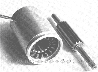
Figure 2.12. Estatory rotor of a stepper motor variable reluctance four-phase-angle and 7.5 º per step.


