2.2.2. Relationship between the dynamic torque and static torque
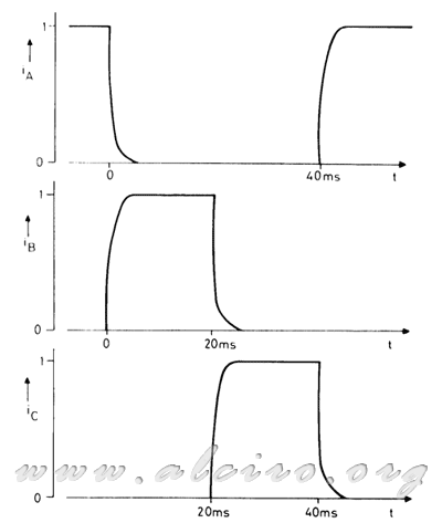
Operating at low frequency current through the motor phases is rectangular. For example in Figure 3.9 the current through the three phases reaches the maximum value since the time constant is 1ms phase and period of excitation is of 20ms at a rate of 50 steps per second. Under these conditions we can deduce the dynamic torque 'pull out' the engine for a particular excitation characteristics.

Figure 3.9. Waveform of the current 50 steps per second for a 3 phase motor, operating with an active phase sequence. The winding time constant is 1ms.
To analyze this problem we assume that the rotor has a high inertia load and that variation in motor torque produces only a small change in engine speed. With these conditions of high inertia, the dynamic torque 'pull out' is equivalent to the average static torque produced by the motor.

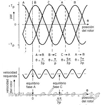
Figure 3.10. Position of the rotor and TIMP conmuación phase no load on the engine.
For a state in constant movement to operate without load, the rotor position and commutation of the phases is illustrated in Figure 3.10 with reference to the characteristics of torque / position of a static three-phase motor operating with an operation sequence active phase. It starts at the equilibrium position of phase A (Θ = 0), the flow is stable at face value and the rotor has a speed that it moves to the required position. When the rotor moves forward the torque produced by the engine is negative and the system slows down until the rotor reaches the position Θ = π / (3 * d) where the speed is minimal. At this point the excitement was almost instantly switches of phase A to phase B, and the new engine produces a positive torque, causing the system to accelerate towards the equilibrium position of phase B at Θ = (2 * π ) / (3 * d). Engine speed increases under the influence of positive torque and the equilibrium position is achieved with maximum speed. The cycle is repeated with the engine producing a negative torque past the equilibrium position and the excitation is switched from phase B to phase C at position Θ = π / / d. During the excitation of each motor phase produces positive torque and negative in the average torque output. The rotor produces a torque balance on the zero line and as a result, no torque delivery to accelerate the rotor, maintaining the average speed equivalent to the sequence of excitation pulses.
The system is in equilibrium position because the small load torque slows the rotor with respect to changes in arousal. With an increase of the rotor load torque increases its delay with respect to excitation, resulting in the positive torque produced by the engine is greater than the negative, with a mean positive torque to overcome that as load is applied .

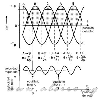
Figure 3.11. Position of the rotor and TIMP conmuación phase for maximum load.
Now consider the effect of applying a load torque equal to the value of dynamic torque for the engine to produce maximum torque. Figure 3.11 shows the rotor delayed with respect to load torque and the engine produces positive torque for each period of excitation. The position of equilibrium for the excited phase is never reached because it produces more torque switching positive for the next phase and position of the step is increased. For example, when the excitation is transferred from phase A to phase B for Θ =- π / (6 * d). The torque generated in this sequence decreases as the system slows down. In the middle of the step motor torque has the maximum value being higher than the load torque so that the system is accelerating.
With applied load torque equal to the dynamic pair, the system is in unstable equilibrium if a small increase in load slows the rotor losing synchronism with the excitation field, which blocks the motor. Under these conditions the rotor torque is at the limit of acceptable delay.
In Figure 3.11 the torque characteristics / position for phase A is:
) (3.12)
(3.12)
If the phase A is connected to Θ =- (5 * π) / (6 * d) and logs in Θ =- π / (6 * d) for maximum torque, then the dynamic torque for a three-phase motor operating with a sequence of an active phase, is getting the average of TA in this range.
}\ =\ \frac{\int_{-5\pi /6p}^{-\pi /6p}-T_p*sin(d\theta )\partial \theta }{(-\frac{\pi }{6d})-(-\frac{5\pi }{6d'})}\ =\ 0.83T_p) (3.13)
(3.13)
You can apply the same method to calculate the dynamic torque for other sequences of excitement.


