2.2. Dynamic Characteristics
The characteristics of dynamic behavior that we relate motor speed and torque, and can be derived from these start-up, stop, and acceleration.
2.2.1. Curves / torque / frequency
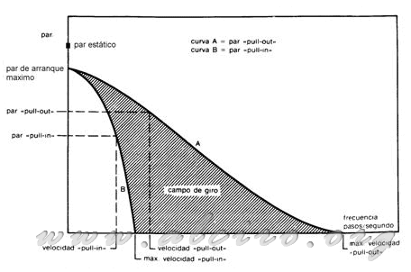
The stepper motors are used for positioning in mechanical systems that require precise control of the step, the torque generated must be sufficient to drag the loads to which they are subjected, in sequence of acceleration, deceleration or constant speed work . Working conditions, need for speed and acceleration on the choice of engine must meet the requirements of torque / speed required. To carry out the election, we have to base cornering speed / torque provided by the manufacturer. These are formed by two curves, the first so-called 'pull in' indicates the pair start or stop without losing steps, depending on the speed of start or stop with the engine at rest, the second 'pull out 'gives us the maximum torque when the engine is running. Among the curve 'pull in' and the 'pull out' we have the acceleration deceleration area is known as rotating field or drop zone.

Figure 3.7. Curves dynamics.
Figure 3.7 shows the typical curves of a stepper motor, the curve 'pull in' the area is bounded start / stop, indicating its extreme maximum starting frequency and the maximum starting torque. For the engine to start, you have to confront the starting curve 'pull in' with the resistive torque of the system and find the maximum starting frequency, above this the engine torque delivery is lower than in the burden , are blocked. Curve 'pull out' sets the maximum torque and maximum frequency. If the ratio torque / frequency falls outside the limits of the curve 'pull out' the rotor loses the synchronism of the magnetic field generated by the excitation, leading to loss of steps or full stop, leaving the engine in a state of oscillation without movement.

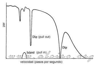
Figure 3.7. Example of characteristic curves with dips and islands.
The torque curves / often have a number of instabilities in the low frequency of 10Hz to 100Hz, varying by type of motor. L Figure 3.8 shows the so-called 'dips' down valleys and slopes of the curve 'pull out'. These occur for mechanical resonance to these experiences the motor frequency can be varied by the action of the mechanical system load is attached to the motor shaft. These 'dips' cause a dramatic decrease in torque generated by the engine, even the total cancellation, leading to the arrest of this with minimum loads or working in a vacuum.
Another type of instability is the so-called 'islands' islands that are part of the curve 'pull in'. In these areas the engine is not able to boot and starts to oscillate as applied to the shaft has a minimum of friction torque.
Above a frequency of 100Hz and to limit the engine speed characteristic curves 'pull in' and 'pull out' are more or less uniform and do not usually have this kind of irregularities, so that the motor usually start and stop at a minimum rate of 100Hz, keeping the engine speed is always above it. However these effects can be minimized by flywheels 'dampers' coupled to the motor shaft, look at Section 3.2.4.
Another way to solve this problem is to work in half steps 'half stepping' or better in microstep, as this type of operation the movement of the rotor is not incremental step by step with sudden angular jumps, it is almost linear, eliminating the mechanical resonances that cause instability problems, look at Section 3.2.3.


